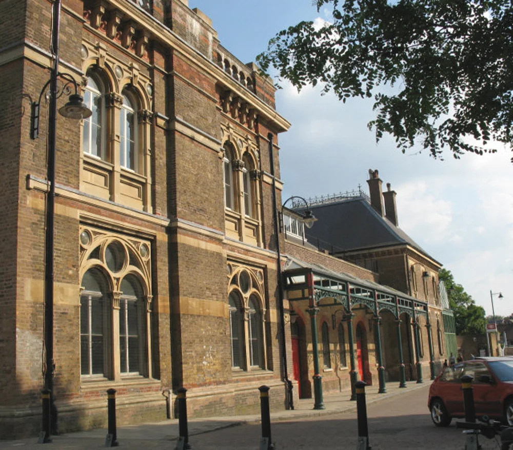
Restoration of British Rail- Crystal Palace Low Level Station
Architecture Firm: John Millard t/a Helix Studio
Client: British Rail/ Roseberry's Fine Art
Site: Crystal Palace Low Level Station, Sydenham, London
Date of Project: 1990- 1991
Project Summary: This study, sponsored by Roseberry Fine Art- tenant of the Crystal Palace Low Level Station Booking Hall resulted in the renovation of this historic Joseph Paxton designed station owned by British Rail and subject to English Heritage Listed Building Status as a Grade 2 listed building. In addition to the renovation of the existing station, a development project by John Millard proposing a 130,000 sf rail and road vehicle museum and professional offices and corporate accommodation accompanied the restoration project.
John Millard's Role- I executed two contracts with the client- one contract for Historic Buildings, Repairs and Conservation Work and one contract for A Development of the Low Level Station owned by British Rail. These contracts were executed after a significant amount of investigation into the project together with my previous employers at Arup Associates and an extensive amount of work carried out for my Diploma Portfolio at The Architectural Association School of Architecture. I carried out a measured survey of the entire Low Level Station and produced measured drawings by hand. I employed one other architect to carry out these drawings. His name is Elden Croy, AA Dipl. RIBA.
Table of Contents;
1. 1871 Ordnance Survey Map
2. History of the Low Level Station
3. Isometric of the Low Level Station (DRWG. S110A)
4. Exploded Isometric (DRWG. S110B)
5. Isometric Section taken at Vault Level (DRWG. Sl10C)
6. Contemporary Transport Services
7. Transport Services Plan (DRWG. S100)
8. The Crystal Palace Park Grounds and Occupants
9. Crystal Palace Park Plan (DRWG. S101)
10. Recommendations for Development of the L.L.S.
11. Existing Plan of Southwestern Park Edge. (DRWG. S102)
12. Existing Pedestrian and Vehicular Access Plan (DRWG.
13. Access Proposals 1 & 2
14. Plan of Proposal 1 (DRWG. S210A)
15. Plan of Proposal 2 (DRWG. S211A)
16. Conclusion of Access Report
17. Plan of Proposal 3 (DRWG. S212A)
History of the Low Level Rail Station;
An Act of Parliament authorized the Crystal Palace branch line on 8th July, 1853 shortly after work began on reconstruction of the Crystal Palace on Sydenham Hill, 5 August, 1852. Originally the Station was designed as a terminus, but another Act of 4th August 1853 enabled the West End of London & Crystal Palace Railway to extend a line from Wandsworth to five intermediary destinations and finally nthrough a 745 foot long tunnel to the west wall of the Low Level Station. West-bound trains began arriving at the final destination of the Thames at Battersea Wharf on 29th March, 1858. The building itself was designed in three sections by Frederick Dale Banister and Whitney Mannering. These sections comprised;
1) Booking Hall & General Waiting Room 69ft. X 35ft. covered by a semicircular cast-iron vault with a clerestory 12ft. wide and 4ft. high along the crest. The floor was paved i~ Minton Tiles and incorporated into a concrete raft which was supported by cast iron girders and jack arches of nine inch brickwork.
2) A 2-storey tower immediately to the north containing two corridors each 41ft. X 11ft. 1st and 2nd class Ladies waiting rooms and lavatories each 23ft. X 15ft. and lSft.X 17ft. respectively. On the ground floor, a large dining room was provided with a refreshment bar and a cloakroom 20ft. X 15ft. On the first floor, a second dining room was provided together with kitchens and associated rooms. The roof was a very high pitched mansard roof covered in zinc and topped by a decorative wrought iron balustrade round the crowning square.
3) A 2-storey tower immediately to the south containing a booking office, a telegraph office and waiting rooms with first, second and third class waiting rooms and lavatories. Stationmaster's accommodation on the first floor comprised a living room, four bedrooms and a kitchen plus lavatory. The road bridge which spanned between Anerly Hill and the Palace Grounds was widened by 10ft. to accommodate a porte cochere of five cast-iron glazed bays. History of the Low Level Station (continued) ... The Low Level Station offered four tracks which were served by three double faced island platforms. The central platform served the two roads which proceeded through to West Norwood. The outer two tracks terminated at the Low Level Station where 10,000 passengers were delivered each weekday. The platforms were contained by two 456ft. long retaining walls with a third spinewall running down the centre of the station, dividing the central platform and supporting two cast-iron glazed vaults which sheltered the entire length of the platforms. The breadth of this space was 115ft. totaling some 52,000sq.ft. of area and terminating with a tall space covered by a series of 3 warren truss sheds with clerestories at each ridge. This space contained 4 brick stairs rising 22ft. to the booking hall. Below the stairs, there existed accommodation for railworkers. At the opposite end of the platforms, a turntable was placed central to the through tracks. Drawings which illustrate the present day Low Level Station can be found on pages 4, 5 & 6 of this report. On page 4, a three dimensional drawing shows the station and its immediate environs including the station approach road and neighboring Ledrington Road. The small chapel which exists from Victorian times is indicated by a number 9 on the legend and on the chapel itself on the drawing. In this way the other features of the building which still exist can be located in the legend with the exception of the Mansard Roof over the South Tower which no longer exists but has been drawn here to show a proposed restoration of that element. On page 5, the three dimensional drawing has projected certain elements of the building into space in order that the breakdown of the building's interior can be better understood.On page 6, only the sub-structure of the station can be understood. The purpose of this drawing is to assist with any conversation regarding use of these spaces for access or accommodation in the future.
Contemporary Transport Services to the Low Level Station;
The Site of the Low Level Station is indicated at the centre of Drawing S100 on page 8. The Low Level Station remains in use by British Rail. Of the four lines which served the Low Level Station, one line shall remain in use. Additionally the modern day station offers a service on the two Norwood lines. These lines offer mainline Victoria to Norwood Junction/ Beckenham Junction services operating eight passenger trains per hour increasing to eleven during peak hours. There is a main line service to London Bridge with connections at New Cross Gate for Docklands. The Thameslink service also offers connections from Crystal Palace with Blackfriars, St.Paul's, Farringdon, King's Cross and The North as well as southern destinations including West Croydon, Epsom and Guildford.
The Crystal Palace Park Grounds and Occupants;
The National Sports Center, administered by The Sports Council, is a primary tenant of the Crystal Palace Grounds. The grounds occupied by The Sports Council are indicated by a red line surrounding the sports facilities due north of the Low Level Station Site in drawing S101 on page 10. This lease line encompasses the access requirements of the sports facilities but does not include adequate parking for the day to day requirements of the administrative personnel at the Jubilee Stand nor for the needs of mass spectator events in the sports arena. The Sports Council lease expires in the year 2004 and is currently being renegotiated with Bromley, the owners of the palace grounds.
Another occupant of the site includes a caravan site which has recently moved from a site in the park set aside by Bromley Council for future development. The caravan park has consolidated its position in a landscaped remote area indicated by a red leaseline on drawing S101 in the north-western corner of the park.
The site set aside for future development is indicated on DRWG. S101 as a Hotel Site. This is located in the western extreme of The Park. Holiday Inn is about to become guarantor of a major leisure development including a 150 bedroom hotel, a four screen cinema complex, a health club, indoor and outdoor tennis courts plus a 600 car parking facility.
The primary occupant of The Park is the owner of the park, Bromley Council. Bromley's major interest in the park is that The Crystal Palace Park be retained by the comunity for leisure use. Any development of this land must therefor conform to the Parliamentary Act which protects the park from purely commercial use. The numerous attractions provided by Bromley include a concert bowl, landscape gardens playing fields, a cafe, archaeological exhibits, a children's playground, a museum and a zoo.
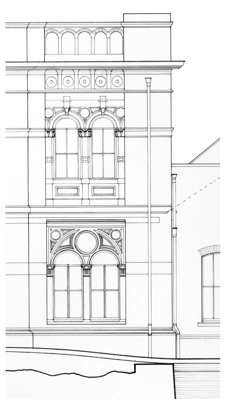
Figure 1: Detail of foiled window bay in the North Tower
- these windows date back to 1875 (Drawing by John Millard)

Figure 2: Measured drawing of the North Elevation
-shows what remained of the station absent the Mansard Roof over the North Tower and the Porte Cochere in front of the Ticketing Office. (Drawing by John Millard)
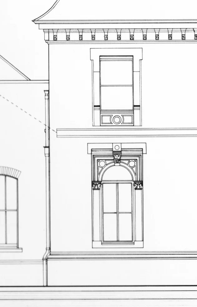
Figure 3: Detail of foiled window bay in the South Tower- these windows date back to 1875
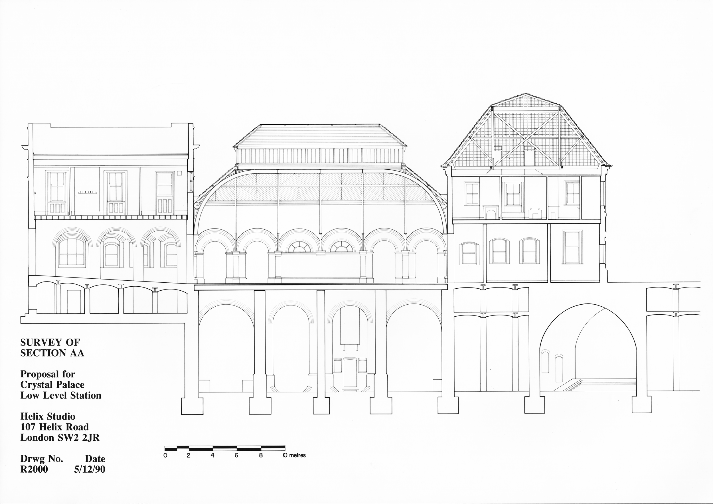
Figure 4: Measured Section through Low Level Station
-shows extent of brick vaults that form the bridge under which rail traffic passes from the tunnel under Sydenham Hill to Bromely. (Drawing by Elden Croy)
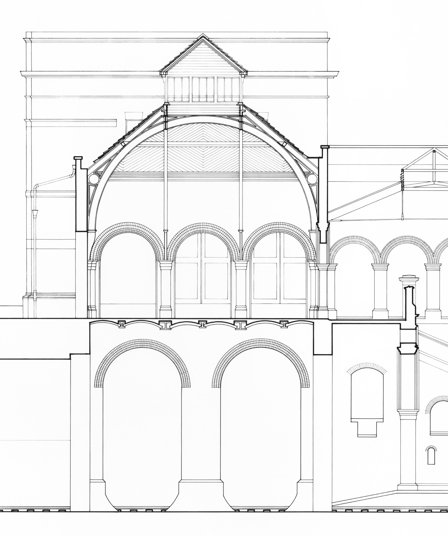
Figure 5: Excerpt from section facing east through train shed and ticketing hall...
shows brick "jack arches" that support elevated ticketing level/ mezzanine to stairs leading down to platforms. (Drawing by John Millard)
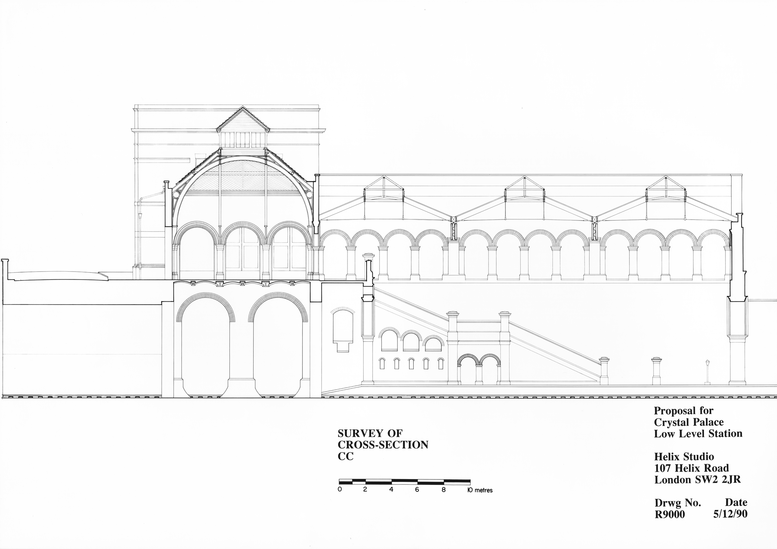
Figure 6: Measured Survey Drawing of Section facing east...
-section shows Train Shed Roof Structure that has now been restored (Drawing by John Millard)
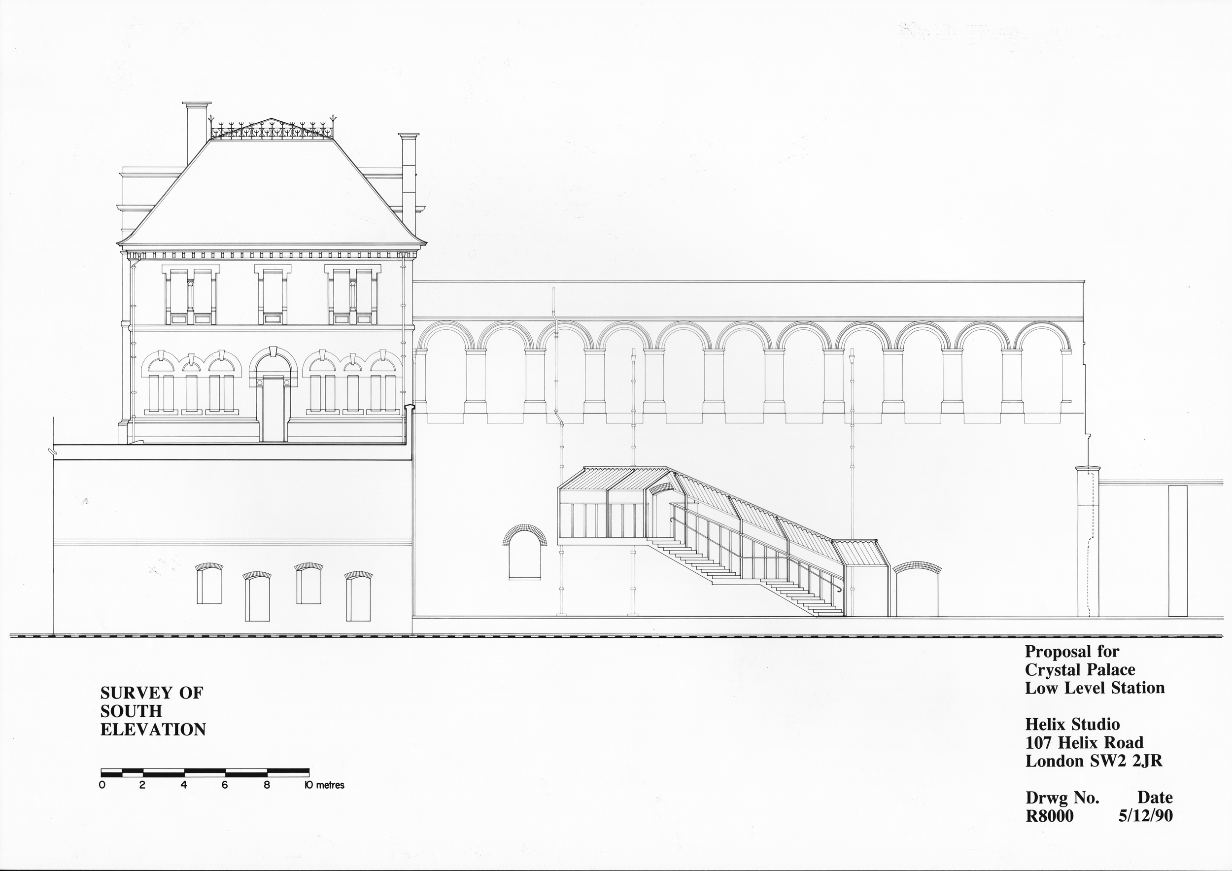
Figure 7: Measured Survey Drawing showing West Elevation...
...showing stairs from train shed leading to the Bromely Spur (Drawing by Elden Croy)
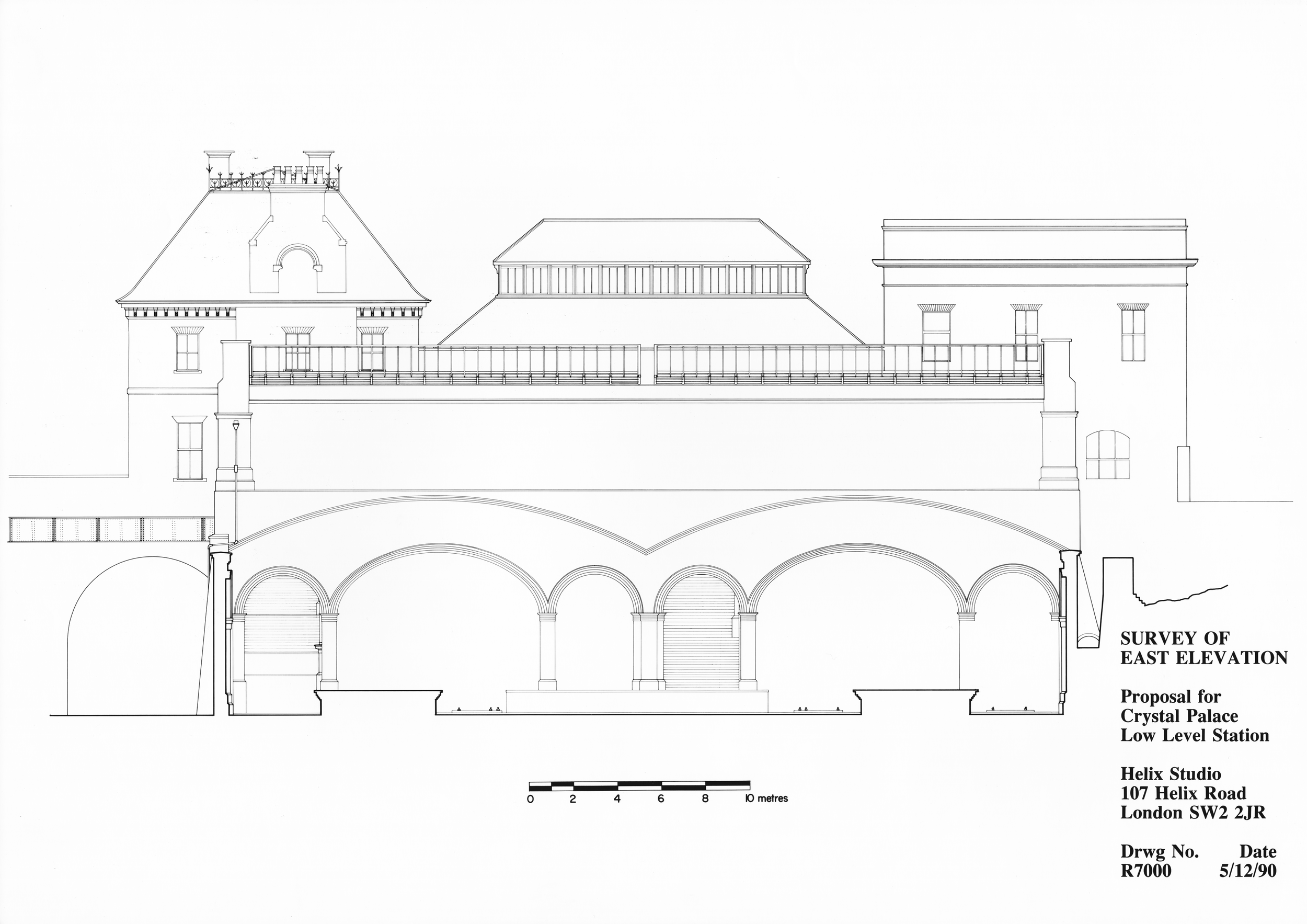
Figure 8: Measured Survey Drawing showing the South Elevation...
-drawing shows curved trace lines where platform canopies covered the trains for loading and unloading (Drawing by John Millard)

Figure 9: Interior Elevation of Train Shed South Wall...
Drawing shows exact fenestration of wall that would define part of rail museum. (Drawing by John Millard)

Figure 10: Measured Survey Drawing showing plan of rail level...
- system of arches, walls and retaining walls that form the plinth of the bridge structure and brick stair cases (Drawing by Elden Croy)
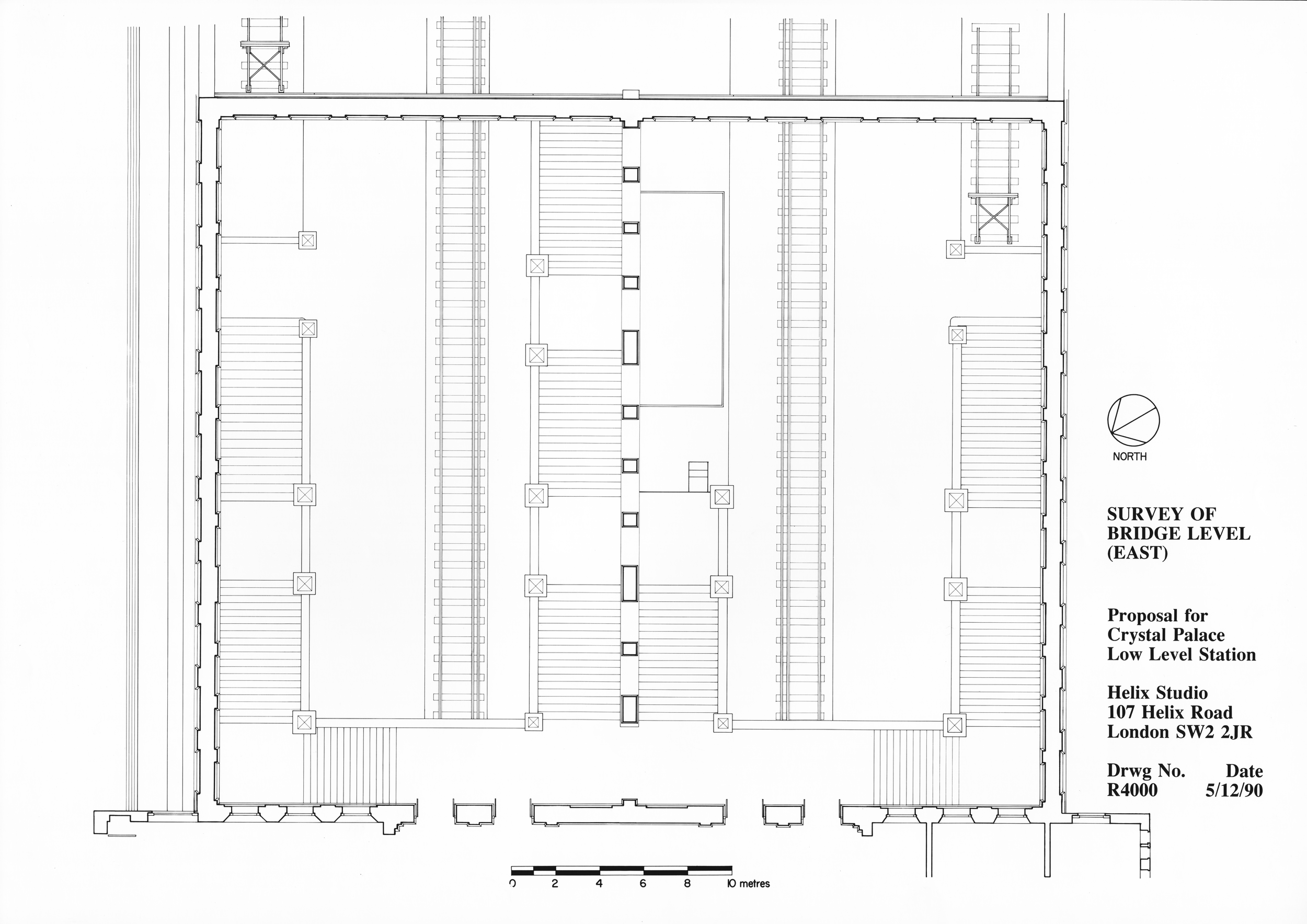
Figure 11: Measured Survey Drawing showing plan of upper Train Shed...
- this space is over-sailed by iron trusses that support the shed roofs and drainage systems that carry water from the roofs to scuppers in the parapet. (Drawing by John Millard)

Figure 12: Measured Survey Drawing of East Elevation...
- shows exterior grade at retaining wall outside train shed in Crystal Palace Park (Drawing by Elden Croy)

Figure 13: Measured survey drawing showing bridge level plan of ticketing hall, road bridge approach and rails below...
Measured Survey Drawing of North Tower (left) and South Tower (right) bridge level plans with Ticketing Hall (center) and bridge approach to the station (Train Shed omitted from plan) shows the only heated space in the entire station. (Drawing by John Millard)
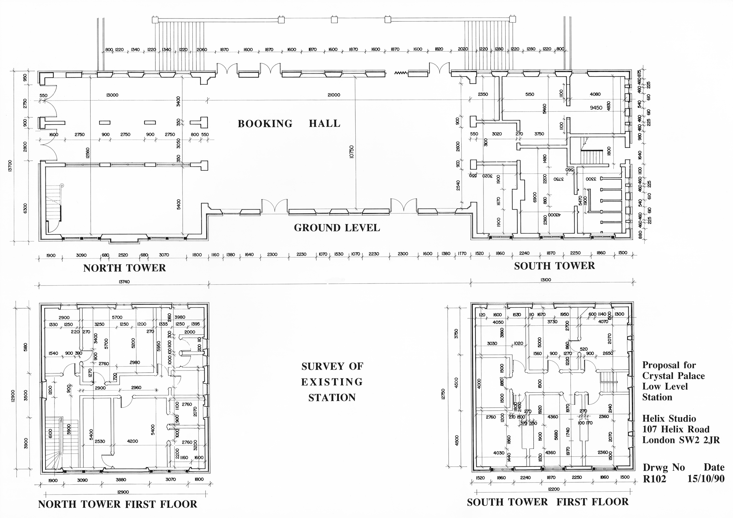
Figure 14: Measured survey drawing of upper level floors of South and North Towers
These drawings were used by British Rail to procure labor from renovation contractors who restored the building after years of dereliction. (Drawing by John Millard)

Figure 15: Measured survey drawing showing upper levels of towers and schedule of areas for usable space.
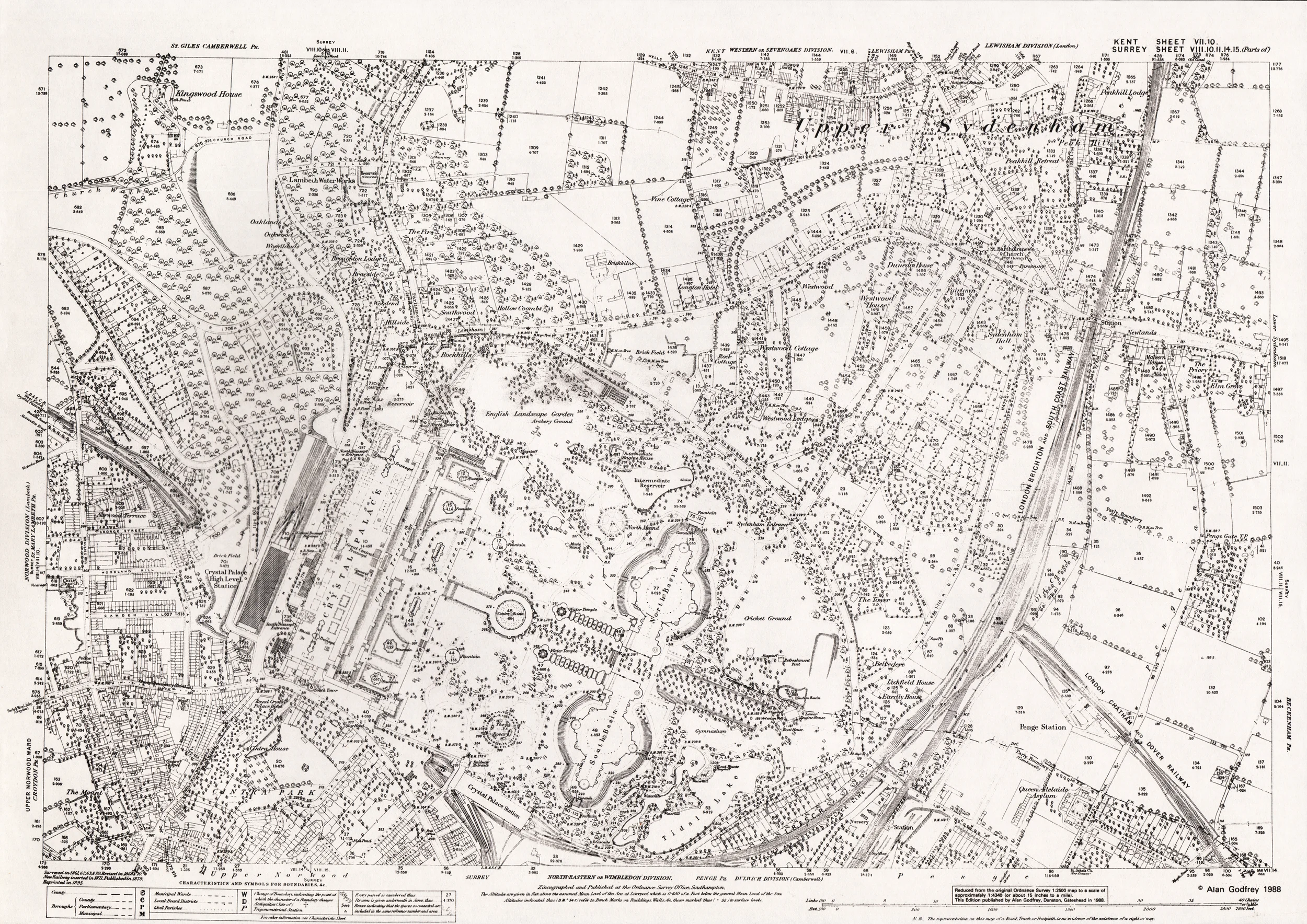
Figure 16: 1871 Ordinance Survey Map of Sydenham Hill.

